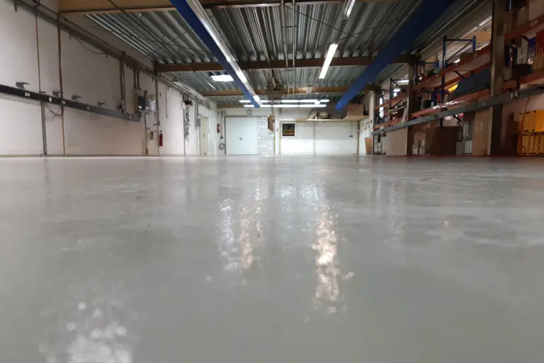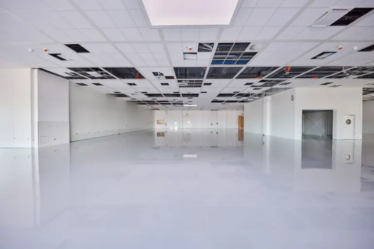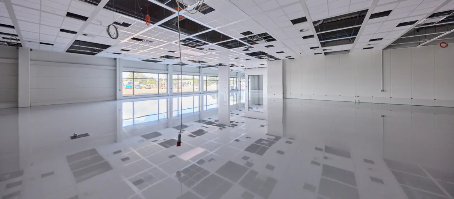
Conductive floor coatings protect people and electronics
FAQ: Key information at a glance
The term ‘Electrostatic Discharge’ (ESD) refers to an electrostatic discharge.
ESD (Electrostatic Discharge) is dangerous because it generates invisible voltage spikes that can destroy sensitive electronics and cause fires or even explosions.
ESD protection measures are varied. The establishment of a protected zone, known as an ESD-protected area, is crucial. Within this zone, all materials used must be dissipative and earthed to the same potential. This allows electrostatic charges and potential differences to be specifically prevented. Among other things, dissipative flooring is used in areas suitable for foot traffic in combination with special ESD safety footwear.
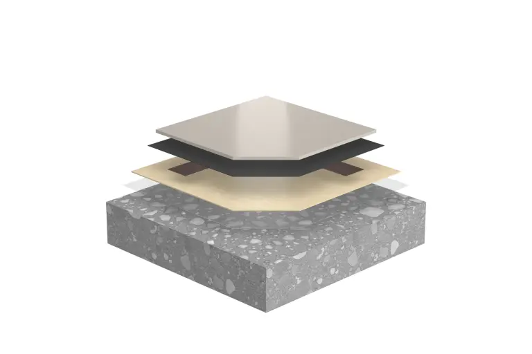
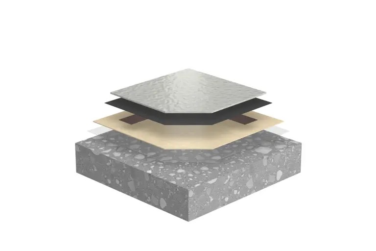
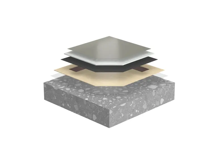
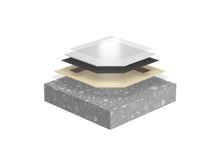
In a coating system, the priming coat forms an insulating layer on the concrete substrate. A conductive intermediate layer is therefore necessary. This conductive layer allows electrostatic charges to be ‘channelled’ to earth with a constant resistance. An ESD conductive layer (electrostatically conductive layer) usually consists of an epoxy resin matrix mixed with conductive particles (fillers).
Which standards and guidelines govern electrostatic discharge (ESD) and explosion prevention for floor coverings?
Scope of application for ESD protection:
• DIN EN IEC 61340-5-1 (06.2025): Protection of electronic components against electrostatic phenomena – General requirements
• DIN EN 61340-4-1 (April 2016): Electrical resistance of floor coverings and installed floors
• DIN EN 61340-4-5 (April 2019) Electrostatics – Part 4-5: Standard test methods for specific applications – Methods for characterising the electrostatic protective effect of footwear and the floor in combination with a person
Scope of application: explosion prevention:
• TRGS (Technical Rules for Hazardous Substances) 727: Prevention of ignition hazards resulting from electrostatic charges (published in the GMBl [Joint Ministerial Gazette] No. 12–17 of 26 April 2016, pp. 256–314; corrected in GMBI No. 31 of 29 July 2016, p. 623)
• DIN EN 1081 (01.2021): Elastic floor coverings – Determination of electrical resistance
Scope of application: personal protection:
• DIN VDE 0100-410 (10.2018): Installation of low-voltage systems – Part 4-41: Protective measures – Protection against electric shock
• DIN VDE 0100-600 (June 2017): Annex B
ESD protection in production facilities
ESD floors reduce risk of electrostatic discharges and dust explosions
Conductive floor coatings provide ESD (electrostatic discharge) protection in production facilities, among other things, and thus reduce the risk of damage to electronic components caused by electrostatic discharges. Due to the conductivity, the majority of the electrostatic potential is discharged via the grounding. The sophisticated StoFloor ESD systems can be adapted to all building-specific requirements.

They already trust us:
▪ Fraport AG
▪ Fraunhofer ISE
▪ Pilatus Flugzeugwerke AG – pilatus-aircraft.com
▪ Robert Bosch GmbH
▪ Škoda Auto a.s.
▪ Strüby Unternehmungen
▪ Thermoplan AG
▪ Volkswagen AG
▪ Zollner Elektronik AG

Protection of electronics and people
Electrical conductivity floor coatings play an important role in defect-free end products and protect people from electric shock by preventing electrostatic discharge. A distinction is made between the protection of electronics, personal protection and explosion prevention.
Electrostatic discharge protection in electronics
Electrostatic discharge protection is important in electronics production, but also in cleanrooms or operating theatres. Electrostatic potentials can attract particles (dust) and thus cause contamination in the cleanroom. This can cause irreparable damage to electronically sensitive building elements.
Avoid sparks as a source of ignition
Installations with potentially explosive atmospheres, such as grain mills, chemical and fertiliser storage facilities or ammunition factories, have normative requirements for structural measures, as sparks caused by electrostatic discharge can serve as an ignition source and trigger explosions.
In sensitive production areas, electrostatically protected workstations are part of the basic equipment with dissipative chairs, tables, shoes, wrist earthing straps, ionisers and a conductive floor coating. This coating conducts away most of the electrostatic potential generated by people or transport objects to the earthing system. To guarantee the function of the coating system, its components must be perfectly harmonised.
The system components and their function
Usually, cementitious substrates such as cement screeds or concrete, and more rarely magnesia or anhydrite screeds, are coated. Substrates that are soaked from behind require a diffusion-open system and thermoplastic substrates, such as mastic asphalt, require a viscoplastic system.
The discharge resistance of a conductive coating system results primarily from the layer thickness of the top coat. In order to achieve a uniform resistance over the entire surface, this must be even. For this reason, it is advisable to apply a levelling filler after the primer coat on rough and uneven substrates. This is obtained by filling the primer with fire-dried quartz sand.
The conductive properties of concrete diminish over time due to drying processes. In addition, the primer acts as an insulating layer. Therefore, a conductive intermediate layer is necessary. This conductive layer allows the electrostatic charges to flow off "channelled" to earth with constant resistance. It usually consists of a soot-filled, watery epoxy resin dispersion.
The top layer of conventional systems gets its conductive properties from carbon fibres. So-called volume-conductive coatings, on the other hand, have special conductive fillers that give the systems a much more homogeneous conductivity.
Conventional systems with carbon fibres meet the requirements for explosion protection, but not the current requirements for ESD protection. Therefore, they receive additional pigmented, conductive sealants that are highly abrasion-resistant and have a certain horizontal conductivity. In this way, they homogenise the conductivity of the entire system and dissipate any charges that arise not only vertically but also horizontally.
StoDivers LS conducting set
Installation instruction- Selection of the connection points
∙ Approx. 100 m2 of jointless surface can be conducted away per earth lead.
∙ Arrange connection points in areas subject to low mechanical loads, approx. 3 - 10 cm away from walls or supports.
∙ Distribute connection points evenly, distance to the next connection point < 20 m
Download the detailed instructions here